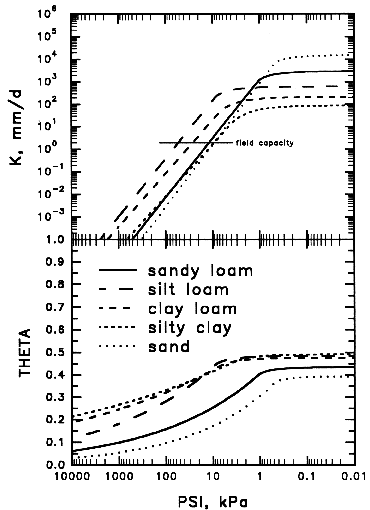
 Fig. KPT- 1. Clapp-Hornberger (1978) curves for
selected texture classes. The horizontal line shows an obsolete definition of
field capacity at 2 mm/d.
Fig. KPT- 1. Clapp-Hornberger (1978) curves for
selected texture classes. The horizontal line shows an obsolete definition of
field capacity at 2 mm/d.May 23, 2018
Soil Water Relationships -
SOILPAR - SOILVAR -
FPSIM - FDPSIDW
Clapp-Hornberger Parameters -
Field Capacity in BROOK90 -
Parameter Selection
This section describes the soil water properties in BROOK90, and the four routines used to calculate their values. The section also discusses the concept of field capacity, and how it is or is not used. Finally the section comments on the selection of soil water parameters and the use of the menu item EditParameters-KPTGraph.
This section uses both the standard algebraic notation for soil water variables as in Clapp and Hornberger(1978) and the BROOK90 variable names. The correspondence is
| θ | THETA | W | WETNES | ψ | PSIM | K | KK | b | BEXP |
| θf | THETAF | Wf | WETF | ψf | PSIF | Kf | KF | n | CHN |
| θs | THSAT | Wi | WETINF | ψi | PSIINF | Ks | KSAT | m | CHM |
| T | THICK | S | STONEF |
Functional relationships among soil-water content, θ, matric potential, ψ, and hydraulic conductivity, K, are required for any simulation that moves water through the soil. There is a rather vast literature on this subject, though much of it emphasizes agricultural soils rather than natural soils, which are less disturbed and higher in organic matter. BROOK90 uses a modification of the Campbell (1974) expressions with the near-saturation interpolation of Clapp and Hornberger (1978).
The wetness, W, or saturation fraction, is defined as the fraction of the pore space that is filled with water, or
(1) W = (θ - θr) / θs - θr)
where θs is the saturated water content, or porosity, and θr is the "residual water content".
The classic expressions of Brooks and Corey (1964) are
(2) ψ = ψs W-b
where b is a parameter and ψs is the potential to which the curve extrapolates when W = 1 (air-entry potential), and
(3) K = Ks W2b+3
where Ks is the saturated hydraulic conductivity.
With the assumption that θr is usually so small it can be set to zero, these equations are usually attributed to Campbell (1974). Wösten and van Genuchten (1988) state that θr can be set to zero "without significantly affecting the accuracy of the results". The Campbell form (θr = 0) is used in BROOK90 and by Clapp and Hornberger (1978).
Equation (2) fails as the soil approaches saturation, that is, as W approaches 1, because ψ at saturation must be 0, not ψs. In this "near saturation region", Clapp and Hornberger (1978) suggest that the parabolic expression
(4) ψ = -m (W - n) (1 - W)
provides an appropriate approximation, and holds above an inflection wetness, Wi, at which the change to parabolic form occurs. They obtained the two parameters, m, and n, by matching (2) and (4) and their first derivatives at W = Wi, leading to
(5) m = -ψi [1 / (1 - Wi) - b / Wi ] / (1 - Wi)
(6) n = 2 Wi - 1 + (b ψi / m Wi)
where ψi is ψ at Wi obtained from (2). They suggest that Wi can be taken as 0.92 for all soils, but varying it allows a closer agreement with the vanGenuchten (1980) equation. However, Wi must be greater than b/(1+b). (Note that in Clapp and Hornberger (1978) ψ is always positive whereas here ψ is inherently negative.) Equation (3) does not inflect but holds up to Ks at θs .
The more complicated expressions of vanGenuchten (1980) are frequently used as an alternative to the Brooks-Corey equations. Conversion of parameters between the two forms can be accomplished (Ma and others 1999) but are less satisfactory because of the abrupt break at saturation in the Brooks-Corey expression. The Clapp-Hornberger curve shape should agree better with vanGenuchten than Brooks-Corey does, especially if Wi is allowed to vary, but I do not know of any direct comparison. Substitution of other relationships, such as van Genuchten in BROOK90 could conceptually be done but would require significant reprogramming. More sophisticated relations such as vanGenuchten hardly seem warranted given spatial variation, hysteresis, and the extra computer time required (Ross 1992).
The use of ψs and Ks in (2) and (3) has been questioned (e.g. Yates and others 1992). Especially in forest soils, any field measurement of Ks will actually be a measure of macropore and pipe flow and probably is not directly related to the unsaturated or matrix flow properties. Therefore these equations are modified in BROOK90 to replace ψs and Ks with ψf and Kf at some unsaturated water content, θf . Then θs becomes the only parameter that affects the near saturation region. The modified equations are
(7) ψ = ψf ( W / Wf ) -b
and
(8) K = Kf ( W / Wf ) 2b+3
where Wf = θf / θs is the wetness at θf.
The wetness at which the ψf , Kf , θf "triple point" is specified does not matter (as long as it is less than Wi) and does not affect the simulation of unsaturated flow and transpiration in BROOK90. However, I chose to require that the triple point be at "field capacity" in order to use this value in simulations of soil evaporation (SLVP), source-area flow (SRFL), bypass flow (BYFL), and the output value of root-zone soil-water deficit (ADEF). For more on this bad decision and on the definition and specification of field capacity, see the Field Capacity section below.
The parameters θf , ψf , Kf , Wi , b , θs , soil layer thickness, T, and stone fraction by volume, S, are all provided for each soil layer in the soil parameter file. Subroutine SOILPAR is called at the beginning of a run to calculate more soil water parameters from these.
The gravity potential, ψg, is measured negatively down from zero at the soil surface. For the surface layer it is -ρwg T(1) / 2, where ρw is the density of water and g is the acceleration of gravity. In BROOK90, ρwg (RHOWG) is constant. For the i'th layer
ψg(i) = ψg(i-1) - ρwg [ T(i-1) + T(i) ] / 2.
The maximum possible water content of a layer in mm, i.e. its water-holding capacity or saturation water content (SWATMX) is
SWATMX = T θs (1 - S).
Wf is obtained from (1) using θf (with θr = 0); then ψi is obtained from (7) using Wi ; then m and n are obtained from (5) and (6).
Initial ψ, rather than initial water content, is provided in the initial value file. The initial wetness, or saturation fraction (W), is then obtained by solving (4) and (6) for W, so
| W = 1 | ψ = 0 |
| W = 0.5(1 + n) + 0.5 (n2 - 2n + 1 + 4ψ/m)0.5 | ψi < ψ < 0 |
| W = Wf ( ψ / ψf )-1/b | ψ < ψi |
The total water content in the layer in mm is
The saturated hydraulic conductivity, Ks, is needed in subroutine VERT to prevent excessive conductivities. It is
Ks = Kf ( 1 / Wf ) 2b+3
from (8) with W = 1.
The wetness of each soil layer (WETC) at the minimum plant water potential (PSICR) is calculated. It is the lower limit of available water in the layer, which is used later to calculate the available water in the root zone (AWAT), an output variable. The upper limit of available water in a soil layer is PSIF.
At the beginning of a run and the end of each iteration time-step BROOK90 calls SOILVAR to calculate other soil water variables from ψ, W, and SWATI. For each layer It calculates total potential, ψt, and water content, θ,
ψt = ψ + ψg
θ = W θs
as well as K from (8) and the total sum of SWATI over all layers (SWAT).
FPSIM obtains ψi from Wi for one layer using equation (7) in the unsaturated region and equation (4) in the near-saturation region. This function is used at the end of every iteration. When Wi = 1, then ψi= 0.
FDPSIDW returns dψi/dWi for one layer, which is needed for the selection of iteration time-step. Differentiation of (7) and (4) leads to
dψi / dWi = ( -b ψf / Wf ) ( Wi / Wf )-b-1
in the unsaturated range,
dψi / dWi= m ( 2 Wi - n - 1 )
in the near saturation range, and
dψi / dWi = 0
when the soil is saturated (Wi = 1).
Clapp and Hornberger (1978) grouped a large number of soils by texture class and obtained an average value of each parameter for each class for equations (1), (2), and (3). Table KPT-1 gives their parameters recalculated at field capacity using my "30-48" definition described below. These parameters give the same K-ψ-θ curves as their original parameters. Fig. KPT-1 shows the curves for some textures.
Table KPT-1. Clapp and Hornberger (1978) soil water parameters recalculated at the 30-48 definition of field capacity . The θs values should not be used for forest soils (see Parameter Selection below).
| PSIF | THETAF | THSAT | BEXP | K | WETINF | |
| ψf | θf | θs | b | Kf | Wi | |
| kPa | mm/d | |||||
| sand | -7.0 | 0.188 | 0.395 | 4.05 | 4.0 | 0.92 |
| loamy sand | -3.8 | .203 | .410 | 4.38 | 3.5 | 0.92 |
| sandy loam | -7.9 | .266 | .435 | 4.90 | 5.5 | 0.92 |
| silt loam | -25.0 | .365 | .485 | 5.30 | 13.1 | 0.92 |
| loam | -8.5 | .324 | .451 | 5.39 | 6.3 | 0.92 |
| sandy clay loam | -6.3 | .317 | .420 | 7.12 | 4.2 | 0.92 |
| silty clay loam | -6.0 | .397 | .477 | 7.75 | 4.9 | 0.92 |
| clay loam | -14.8 | .402 | .476 | 8.52 | 7.3 | 0.92 |
| sandy clay | -3.7 | .358 | .426 | 10.40 | 2.9 | 0.93 |
| silty clay | -6.5 | .433 | .492 | 10.40 | 4.2 | 0.93 |
| clay | -7.7 | .425 | .482 | 11.40 | 4.3 | 0.94 |
Fig. KPT- 1. Clapp-Hornberger (1978) curves for
selected texture classes. The horizontal line shows an obsolete definition of
field capacity at 2 mm/d.
Once again, it is important to understand that BROOK90 does NOT use the concept of field capacity in its simulation of unsaturated matrix flow (VRFL) or transpiration (TRAN). However, it does use the field capacity concept in simulation of source-area flow (SRFL), bypass flow (BYFL), soil evaporation (SLVP), and the output value of root-zone soil-water deficit (ADEF).
The requirement in BROOK90 that the K-ψ-θ "triple point" parameters be at "field capacity" for use in SRFL, BYFL, SLVP, and ADEF calculations violates good modeling practice and has caused considerable confusion. If there is ever a Version 5, I will separately specify field capacity and allow setting the Kf-ψf-θf triple point at any wetness.
How should field capacity be specified? The term has been defined in various ways and its usefulness debated for more than half a century. Although now recognized as an arbitrary point on a continuum, the concept remains useful and refuses to go away. Conceptually field capacity separates soil water that drains rapidly from that which does not. It was originally defined qualitatively as the water content of the upper root zone after two days of drainage from near saturation. Quantitatively, field capacity for many years was arbitrarily set at a water potential of -33 kPa (-1/3 bar), but more recently values varying with soil texture in the range of -10 to -33 kPa have been used. Baver, Gardner, and Gardner (1972, p.383) suggested use of a specified drainage rate such as 2 mm/d. For BROOK90 I formerly recommended the similar, but not identical specification of Kf = 2 mm/d, which could be applied to soils with differing properties among horizons. In reality, upper layers drain faster and the lower layers more slowly, so it is necessary to specify the depth at which the change from rapid to slow drainage is determined. Hillel and van Bavel (1976) point out that during gravity drainage θ at 30 cm depth is approximately the same as the mean θ over a root depth of a meter. This suggests a "30-48" definition of field capacity for any given soil material as "the water volume fraction at 30 cm depth after 48 hours of drainage from an initially saturated homogeneous profile with a fixed gravity potential gradient at 2 m depth".
In Federer, Vörösmarty, and Fekete (2003) we used BROOK90 to examine various methods of specifying field capacity. We simulated drainage from initially saturated uniform 2 m profiles using the eleven Clapp and Hornberger (1978) parameter sets in Table KPT-1 and ten more parameter sets from Saxton et al. (1986). We used a profile of 20 identical 10 cm thick layers and shut off all processes in BROOK90 except downward matrix flow with gravity drainage at the bottom. Initial matric potential was set to zero for all layers (saturation). To ensure a good solution for water movement the Fixed parameter DTIMAX was 0.001 d.
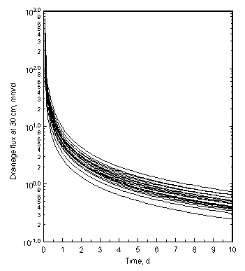 Fig KPT-2a.
Drainage flux at 30 cm
depth for an intially saturated 2-m profile with a gravity gradient at the
bottom for 11 texture classes from Clapp and Hornberger (1978) and 10 texture
classes from Saxton et al. (1986).
Fig KPT-2a.
Drainage flux at 30 cm
depth for an intially saturated 2-m profile with a gravity gradient at the
bottom for 11 texture classes from Clapp and Hornberger (1978) and 10 texture
classes from Saxton et al. (1986).
Drainage flux at 30 cm depth initially drops very rapidly for all 21 soils,
but by 2 days IN ALL SOILS the rapid flux period is over and the soil begins to
drain much more slowly (Fig. KPT-2a). Note the log scale; the transition is
even sharper than it appears here!
Drainage flux at 30-48 ranges from 1.3 to 4.2 mm/d while the hydraulic
conductivity ranges from 2.9 to 13.1 mm/d (not shown). The 2 mm/d drainage flux
suggested as field capacity by Baver, Gardner, and Gardner (1972) is reached at
30 cm in from 1.5 to 4 days.
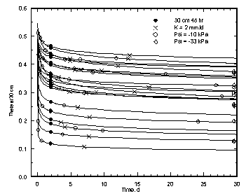 Fig KPT-2b. Volumetric water fraction,
θ, at 30 cm depth for an intially saturated 2-m
profile with a gravity gradient at the bottom for 11 texture classes from
Clapp and Hornberger (1978) and 10 texture classes from Saxton et al.
(1986). Possible field capacity values are shown for 30-48 (black
circle), K=2 mm/d (X), -10 kPa (open circle), and -33 kPa (open
diamond) definitions.
Fig KPT-2b. Volumetric water fraction,
θ, at 30 cm depth for an intially saturated 2-m
profile with a gravity gradient at the bottom for 11 texture classes from
Clapp and Hornberger (1978) and 10 texture classes from Saxton et al.
(1986). Possible field capacity values are shown for 30-48 (black
circle), K=2 mm/d (X), -10 kPa (open circle), and -33 kPa (open
diamond) definitions.
Fig. KPT-2b shows that θ at 30 cm depth also has
changed from rapid decline to slow decline by 48 hours for all soils. The
matric potential at 30-48 ranges from -3 to -51 kPa.
Field capacity at 30 cm by three other definitions occurs after widely
varying times of drainage. Clearly the 30-48 definition provides the most
consistent separation between rapid or "gravitational" drainage and slow
drainage.
The major drawback of the 30-48 definition of field capacity is that it can only be determined by simulation. Perhaps Version 5 of BROOK90 will calculate it from the soil parameters. But for parameter estimation, a more workable definition is desired. For the 21 simulated soils, defining Kf equal to 5 mm/d gives a θf within 0.01 for 15 soils and within 0.01 and 0.02 for 4 more soils. Only the silt loams differ slightly more than 0.02 between the 30-48 and the 5 mm/d definitions. In Fig. KPT-2b these differences are about the diameter of the black dots showing the 30-48 value.
For simulation of actual situations, soil parameters generally should be estimated prior to running BROOK90 and should not be fitted. The method for doing this will vary considerably depending on how much is known about the actual soil materials.
BROOK90 provides graphic display of the K-ψ-θ curves by layer; select EditParameters-KPTGraph to check the reasonableness of the curves. Unreasonable values of soil parameters may cause BROOK90 to crash. The thick K line on the graphs uses the linear left-hand scale; the thin K line is for the log scale on the right. The vertical dashed line indicates PSIF.
Figures KPT-3 through KPT-8 show the sensitivity of the K-ψ-θ curves to each parameter (varied separately) for a soil with KF = 2 mm/d, BEXP = 6.0, PSIF = -10 kPa, THETAF = 0.30, WETINF = 0.92 and THSAT = 0.6.
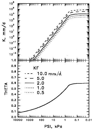 Figure KPT-3. Sensitivity of the
Clapp-Hornberger functions to KF in mm/d.
Figure KPT-3. Sensitivity of the
Clapp-Hornberger functions to KF in mm/d.
The hydraulic conductivity at field capacity
(KF) is difficult to obtain.
If texture class is known and there is no other information, use the value
from Table KPT-1. If texture is not known, use 5 mm/d. Determination of
unsaturated hydraulic conductivity at various water potentials can be done
using a number of laboratory or field methods
(Klute 1986), but for
many hydrologic studies the effort required to carry out these methods is
too great. The value of KF has no effect on the θ
- log ψ relation but raises or lowers K proportionally
in both unsaturated and near saturation regions.
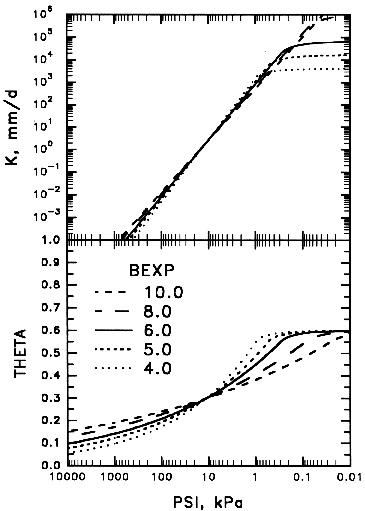 Figure KPT-4. Sensitivity of the
Clapp-Hornberger functions to BEXP.
Figure KPT-4. Sensitivity of the
Clapp-Hornberger functions to BEXP.
The parameter b (BEXP)
can normally be obtained directly from Table KPT-1. If texture is not known,
use a value of 5. BEXP mostly affects the sharpness of curvature and the
slope of the θ - log ψ
relation; it has relatively little effect on K except in the near saturation
range. Values of BEXP above 11.5 will not work unless WETINF
is set higher than 0.92. When measured θ -
ψ data is available, BEXP is the slope of a linear
regression between log θ and log ψ.
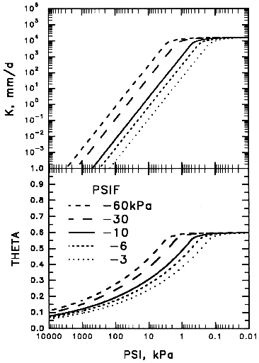 Figure KPT-5. Sensitivity of the
Clapp-Hornberger functions to PSIF.
Figure KPT-5. Sensitivity of the
Clapp-Hornberger functions to PSIF.
In the absence of field data, the water potential at field capacity,
PSIF, can be obtained
from soil texture using Table KPT-1. If texture is not known,
use -10 kPa. Alternatively, measure PSIF with tensiometers as the matric
potential in the field 2 days after thorough wetting. Changes in PSIF move
both the log K - log ψ and the θ - log ψ curves left
or right by the amount of the change in PSIF at THETAF and KF.
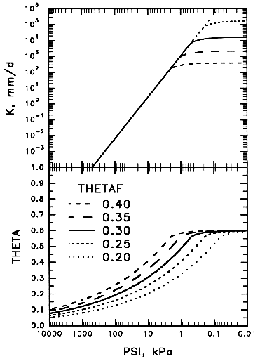 Figure KPT-6. Sensitivity of the
Clapp-Hornberger functions to THETAF.
Figure KPT-6. Sensitivity of the
Clapp-Hornberger functions to THETAF.
The water content (volume fraction) at field capacity
(THETAF) can be estimated
from texture class using Table KPT-1. If no texture information is available,
use THETAF = 0.25 for coarse-textured soils, 0.35 for medium textures, and
0.40 for fine textures. If measured θ-ψ curves are available
from laboratory analysis of soil cores (Klute 1986), THETAF can be chosen
to correspond to PSIF obtained by field measurement of field capacity as
described above. THETAF could also be obtained as measured volumetric water
content on samples collected at the same time that PSIF was measured. Changes
in THETAF move the θ - log ψ curve up or down in the unsaturated
range, and only affect K in the near saturation range. Note that THETAF
should be about 0.40 - 0.85 of THSAT for each layer. Strange things can happen
if the ratio is far outside this range; probably either THETAF or THSAT is
wrong.
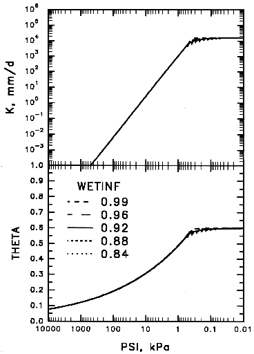 Figure KPT-7. Sensitivity of the
Clapp-Hornberger functions to WETINF.
Figure KPT-7. Sensitivity of the
Clapp-Hornberger functions to WETINF.
WETINF separates the
unsaturated region in which equation (4) applies from the near-saturation
region in which (6) applies. In the absence of any measured data, assume a
value of 0.92. BROOK90 automatically changes the value of WETINF if it
is outside the range of BEXP/(1+BEXP) and 0.999. Results are very insensitive
to this parameter.
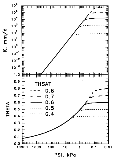 Figure KPT-8. Sensitivity of the
Clapp-Hornberger functions to THSAT.
Figure KPT-8. Sensitivity of the
Clapp-Hornberger functions to THSAT.
The θs (THSAT) values in Table KPT-1 are too low for forest soils. However, the value of THSAT does not matter if the simulated soil never becomes saturated, because with the modified equations THSAT only affects θ, ψ, and K in the near saturation region, θ / θs > Wi , and has no effect in the unsaturated region. In general, mineral soils have a soil particle density, ρm , close to 2.65 Mg/m3. The relation of ρm to soil bulk density, Db , and to θs is
θs = 1 - ( Db / ρm ).
A θs = 0.5 therefore corresponds to a bulk density of 1.32. All the Clapp and Hornberger θs values in Table KPT-1 are lower than this, corresponding to higher bulk density. But in forest soils, bulk density is generally around 1.0 in the root zone, so θs should be around 0.6. Forest soils also have higher organic fraction in some horizons than do agricultural soils. The particle density of organic matter ρo is about 1.3 Mg/m3 (DeVries 1963). Then
θs = 1 - Db { ( Fo / ρo ) + [ ( 1 - Fo ) / ρm ] }
is a better relation where Fo is the organic mass fraction. If Db is not known, it can be estimated from Fo for some forest soils. Federer and others (1993) found that the expression
Db = Dbo Dbm / [ Dbm Fo + Dbo (1 - Fo) ]
works well for coarse and medium textured, glaciated forest soils when Dbm = 1.6 is the bulk density for pure mineral soil (Fo = 0) and Dbo = 0.11 is the bulk density for pure organic matter (Fo = 1). The bulk density and the organic fraction should be calculated after removing the mass and volume of the coarse fraction, which for mineral horizons is greater than 2 mm and for organic horizons is greater than 6 mm (Federer et al. 1993).
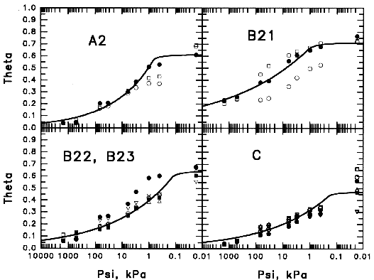 Figure KPT- 9. Volumetric water
content (theta) vs. matric potential (psi) from mineral soil cores in four
horizons at the Hubbard Brook Experimental Forest, New Hampshire. Symbols
indicate different samples.
Figure KPT- 9. Volumetric water
content (theta) vs. matric potential (psi) from mineral soil cores in four
horizons at the Hubbard Brook Experimental Forest, New Hampshire. Symbols
indicate different samples.
Selection of soil water parameters for Hubbard Brook Watershed 6 (parameter
file SHBW6a.txt) provides an example of the above methods. For mineral
horizons, θ-ψ data were measured on core samples using tension table,
pressure chamber, and pressure membrane techniques (Fig KPT-9). For O horizons,
θ-ψ data were obtained on undisturbed 10x10 cm blocks using tension
table and pressure chamber (Fig. KPT-10); such curves for forest O horizons are
very scarce. PSIF was determined from tensiometer measurements in the field to be -12 kPa in surface mineral horizons and -10 kPa in deeper horizons. The -12 kPa value was arbitrarily used for the surface organic horizon. KF was assumed to be 2 mm/d; this probably should be changed to 5 mm/d, which corresponds to the 30-48 definition for Clapp-Hornberger sandy loam (Table KPT-1). WETINF = 0.92 was fixed. THSAT was obtained for each horizon from its bulk density as described above. Finally BEXP (to the nearest 0.5) and THETAF were chosen to fit curves to the data (by eye).
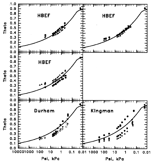 Figure KPT- 10. Volumetric water content vs.
matric potential for block samples of O horizons at three forested locations in
New Hampshire. Symbols indicate different samples.
Figure KPT- 10. Volumetric water content vs.
matric potential for block samples of O horizons at three forested locations in
New Hampshire. Symbols indicate different samples.
![[Compass Brook logo]](cblogo.gif)